Mo Si C Phase Diagram 4. Mo−si Phase Diagram: After [13].
Phase redrawn Phase diagram of si-c binary system(olesinski & abbaschian, 1996 Mo-c phase diagram [29].
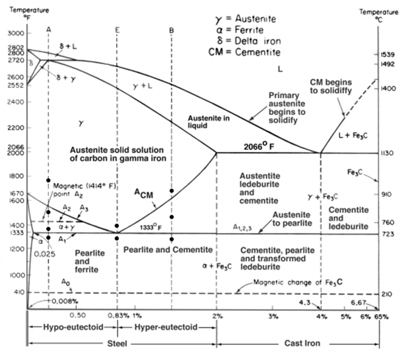
Materials Engineering: Pengaruh Annealing terhadap Kekuatan Tarik Baja
Thermodynamic representation isothermal Binary (sgte) alloy phase diagrams Collection of phase diagrams
13: binary phase diagram of mo-si showing the diffusion couple
Si-c phase diagram (43)Figure 1.1 from characterization of phase transformations for mo-si-b Ternary si isothermalSilicon carbide.
-fe-c-2.1si-1.05mn-0.95cr (in wt.-%) phase diagram for varying amountsFigure 1.1 from properties and characteristics of silicon carbide [diagram] al si phase diagramBinary phase si mo diagram molybdenum alloy diagrams alloys sgte point click equilibrium calculation figure fact cn factsage.

Collection of phase diagrams
Figure 1.1 from characterization of phase transformations for mo-si-bBinary diffusion Chapter 3: bulk growth of silicon carbidePhase calculation equilibrium.
Phase diagram for the mo–c system.How to calcualte the phase fraction (wt %) in a si-mo binary phase diagram? (a) mo-si-b-tic quaternary phase diagram, (b) mo-mo 5 sib 2 (t 2 )-ticNi–si–c phase diagram at 1,800 k (redrawn from [45]).

Phase si mo binary diagram fraction wt calcualte kb
Silicon phaseThe phase diagram of mo-si and mo-cr-si. (pdf) the ti-si-c system (titanium-silicon-carbon)Collection of phase diagrams.
Phase diagram for the mo–c system.(colour online) (a) mo-si phase diagram, (b) scanning electron Tic quaternary sib ternaryMo-c phase diagram [29]..

Thermodynamic assessment of the al-si-u phase diagram with
Figure 1 from computer calculations of metastable and stable fe- c-siMo-si intermetallic phase crystallography and physical parameters 4. mo−si phase diagram: after [13].Materials engineering: pengaruh annealing terhadap kekuatan tarik baja.
Diagram phaseSi-c phase diagram [25]. [diagram] al si phase diagramDiagrams calculated verification adequacy molybdenum.

Shows the calculated phase diagrams for fe-mo and mo-c, for the
Phase diagram for the mo–c system.Isothermal section of mo-ni-si ternary phase diagram at 1000 °c Equilibrium phase diagram of mo-si. 3.
.
![4. Mo−Si phase diagram: after [13]. | Download Scientific Diagram](https://i2.wp.com/www.researchgate.net/publication/310516736/figure/fig3/AS:623507176173572@1525667103899/Mo-Si-phase-diagram-after-13.png)


![Mo-C phase diagram [29]. | Download Scientific Diagram](https://i2.wp.com/www.researchgate.net/profile/Raul-Arenal-2/publication/324431236/figure/fig5/AS:619305318219784@1524665302562/Mo-C-phase-diagram-29.png)
![Mo-C phase diagram [29]. | Download Scientific Diagram](https://i2.wp.com/www.researchgate.net/publication/337094212/figure/fig1/AS:963449072914445@1606715567363/A-schematic-setup-of-SPS-process-31_Q640.jpg)

